Facebook recently wrote about the network architecture they are using in their new Altoona data center facility. If you haven’t read through their article yet, it’s definitely worth the read.
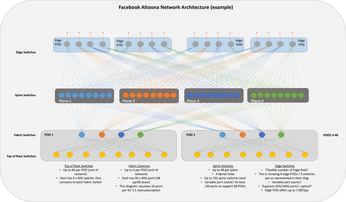
They have a few diagrams that outline the architecture. One of them is in 3-D. 3-D diagrams are always more difficult for my brain to conceptualize (maybe it’s just me), so I re-drew it in a more typical 2-D fashion. There aren’t details on quantity and speeds of ports for the spine and edge switches, so I represented them similar to how they have them in their diagram. For every downward facing port a spine switch has (across the plane), 2300 servers can be added. That’s the amount of servers per pod. 48 servers per rack * 48 racks per pod = 2300 servers. Based on the switch types being used, this number could be more, but I’m using the characteristics of 48 x 10G ports for host facing ports + 4 x 40G ports for uplinks.
My diagram depicts 8 racks in the POD and 8 switches per plane. These numbers would be 48 in a fully built out network/diagram.
Feel free to comment and correct anything I may have mis-represented.
Update 11/17/2014: corrected number of edge pods.
Thanks, Jason
Twitter: @jedelman8